
Introduction into static electricity 
What does static electricity mean?
The phenomenon "static electricity"
- is not observable directly
- can be noticed only due to it’s effects
Everyday life examples:
- Crackling effects during someone is dressing or undressing
- Foil is sticking after winding up
- Lightnings during thunderstorms
- Dust particles attracted by a computer monitor
All these effects are based on static electricity which is an imbalance of static electric charges in or on different objects. The imbalance causes force and discharge actions. To understand these things it is helpful to familiarize with the microscopic structure of objects and materials. All bodies and objects as well as fluids and gases consist of atoms and molecules.

Each atom consists of positively charged protons and negatively charged electrons amongst others. Important for static electricity is the ratio of charges:
a) Number of electrons = number of protons → atom neutral
b) Number of electrons > number of protons → ion negatively charged
c) Number of electrons < number of protons → ion positively charged
In a similar manner the ratio of carriers results in the charge of objects and materials consisting of atoms. If negative carriers prevail, then the object is negatively charged and vice versa.
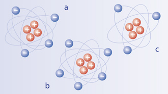

All objects or materilas consist of atoms
Origin of static charges
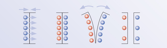
The origin of static charges is a contact phenomenon.
-
As two materials are in contact the surface atoms on each material come into very close proximity with each other (few nanometers). The electrons of the surface atoms can be moved from one material to the other. The direction and the strength of the movement depends on the physical properties of the materials. (Transfer of electrons)
-
If the two materials are separated, then the moved electrons remain partially. This leads to an excess of electrons within the one material (negatively charged) and to a deficiency of electrons within the other (positively charged). These processes occur in conductive as well as insulating materials.
These effects described above appear in solid materials as well as fluids and gases.
Other causes for static charges of objects:
- Strong electric fields (induction)
- Deformation and/or cooling down of materials
- Friction among other things
Factors affecting static electricity
Magnitude and polarity of a static charge are affected by:
- Type of material
- Environmental conditions (humidity, temperature)
- Surface characteristics (roughness)
- Repetition: repeated processes of contact and separation can increase the charge of materials.
- The combination of many charged items can lead to extremely high charges.
- Separation rate e.g. the faster the separation of the materials, the higher charge generated.
Measurement of static charges
Static charges lead to electric fields, whose electric flux lines run from the more negative to the more positive surface. All charged objects, located within or enter such a field, experience a force acting on it. Thus "the hair stand on end" can be explained, which occur after washing and combing.
This force acts on electrons within conductors too and thus it is possible to measure the static charge by special meters. Such instruments are called static meter, static monitor or electrostatic fieldmeter.
Static electricity is usually measured in volts/meter, the unit of electric field.

A well known phenomenon – the "hair stand on end"
Discharging and elimination of static charges
Separated charges tend to balance:
- In conductive, charged materials like metals the negative charges flow to the missing electrodes on the charged areas if these areas are contacted with ground.
- Charged molecules from fluid or air, which contact the charged surface, deliver the lack of charges or absorb charges. This lead to neutralization of surface.
- Neutralization of charges can occur within the material itself, if there are domains of different charge strength and the material has a finite resistance.
Pay attention: Metallic objects can be statically charged too, if they are isolated!
There are different methods to eliminate unwanted static charges:
-
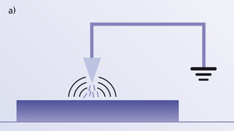
Passive ionization: a grounded conductor prepared with distinct geometry and located in proximity of the charged objects is able to ionize the surrounding air molecules. This air ions lead to discharge in case of contact with the surface. Ionization is caused by electric field between the charged surface and the ionizer. This type of ionizer can reduce the charge very efficiently but never completely neutralize.
-
Radioactive ionization: radioactive sources lead to the ionization of surrounding air. Due to the difficulties and dangers in connection with radioactive materials this method is limited to very specific applications.
-
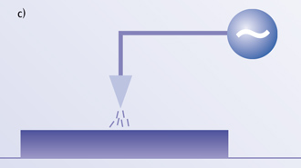
Active ionization: Sharp pins connected to a high voltage power supply act as source of strong electrical fields. These fields lead to ionization of air molecules, which can interact with the charged surface and discharge it. The formation of ionized air molecules by the active ionizer does not depend on the charged object. Thus this system is able to neutralize the charged surface completely contrary to the passive system. A distinction is drawn between alternating current (AC) systems and direct current (DC). Additionally there are DC pulsed systems.
-
Static inhibitors: Excessive charges are drained off in consequence of the wetting with special fluids called static inhibitors. This alternative is limited to applications which are non-sensitive to these fluids.
Passive Ionization
Active Ionization
Applications
Problems caused by charging and its elimination
Different forms of unwanted static charges within industrial processes:
-
Static caused contamination: charged dust particles or particles generated during the production process are attracted by oppositely charged or neutral surfaces and thus result in contamination. This is an impairment of material for the following production process and lead to delay and production stop and scrap rate.
For example surfaces which has to be varnished, must be absolutely dust free. -
Static attraction: Charged objects can cause problems due to attraction among each other or to machine parts.
Example: Errors in the transportation of material -
Static discharges:
Discharge through human body:
Mostly discharge of charged objects does not lead to bodily injury, but to physical discomfort, shock driven actions resulting in accidents and injuries.Discharge in hazardous areas:
Such discharges can result in disastrous effects and therefore have to be absolutely avoided. E. g. areas of operations with solvents or explosive dust.Discharges in electronics or microelectronics (ESD):
Already weak discharges lead to destruction of electronic devices.
Wanted charges and generation
Targeted charging of surfaces
- Generating of different charges
- Temporary connection of different charged surfaces
Examples:
- Face to face contact of foils
- Positioning and adherence of objects
Dust particles on a charged plastic sheet
Difference between AC- and DC-Systems
The Dr. Escherich high voltage driven discharge systems can be divided into two categories as follows, according to each functional principle:
- AC systems resistance coupling
(AC=alternating current) - DC systems, pulsed
(direct current)
AC-Systems
In the case of AC systems the AC network is transformed via a special transformer to the required high voltage of 5 to 8 kV. It is then coupled to the electrode ends of the ionizer. Thereby positive and negative ions are generated alternatively, synchronised with the existing network frequency (normally 50 or 60 Hz).
Coupling of the high voltage to the electrode tips occurs via a high ohm resistance. All systems are personal contact safe – there is no danger to the user if he touches the electrode tips!
These sturdy and extremely low-cost AC systems require a working distance of between 20 and 200 mm in order to achieve greatest discharge efficiency.
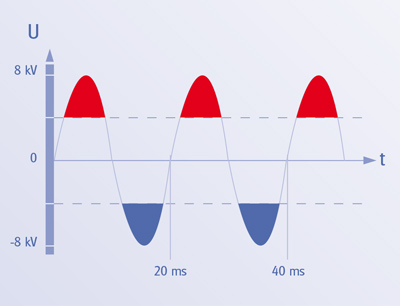
The AC high voltage generates alternately positive ions (red marked area) and negative ions (blue marked area).
DC-Systems
In the case of Dr. Escherich SMART ION DC systems the electrode tips are charged with pulsed high voltage direct current. This direct current high voltage of up to 30 KV is generated via an electronic from a 24 volt DC source. When installing the system, use can thus be made, for instance, of the 24 volt low voltage supply often already available within existing systems and machines. In the case of the SMART ION DC systems the high voltage supply from the low voltage does not occur until the ionizer stage and therefore considerably thinner wiring can be used, making installation much simpler.
In all SMART ION systems, high voltage is coupled to the tips via high ohm resistances in order to limit maximal current and thus guarantee safety for personal contact.
Since the DC systems reach a considerably greater discharge intensity than the AC systems. The systems SMART ION can achieve higher working distances. On the other hand, working distance of less than 200 mm for these systems should be avoided in order to achieve an even discharge (possible with SI100). Since there is no pause in ion emission in the case of DC systems when switching polarities as opposed to AC systems, DC systems are well suited also for considerably higher material feed speeds.
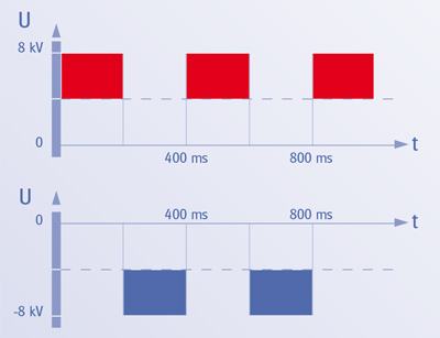
A pulsed DC high voltage generates positive ions at the emitters connected to the positive voltage (red marked area) and negative ions at the emitters connected to the negative voltage (blue marked area). The two different emitter types are arranged alternately at the ionization bar. The frequency is adjustable. The high voltage differs from each models.
Introduction into Industrial Cleaning
Problems with Dust and Particles
Process particles occur not only in the mechanical processing of components but from dust, fibres and particles also from the ambient air, from the operators and from incorrect packaging and transport which can be deposited on the product surfaces.
This can lead to a high scrap rate or costly re-working. Due to the ever increasing demands for technical cleanliness and quality assurance of the product, analyses of the typical practical sources of contamination are unavoidable.
Types of Contamination
Classification according to origin
- Manufacturing process (filings, grinding dust, wear debris etc.)
- Equipment (wear debris etc.)
- Additives (release agents, lubricants, etc.)
- Environment (dust, soot, pollen etc.)
- Personnel (hairs, fibres, fingerprints etc.)
- Packaging (wear debris, fibres etc.)
Classification according to composition
- Inorganic or organic particles
- Metals, minerals, ceramic, plastic, natural substances
- Greases, oils
Classification according to aggregate state
- Solid
- Fluid
- Adhesive, paste-like
Classification according to chemical/physical properties
- Mechanical (abrasive, greasy, adhesive etc.)
- Chemical (polar/non-polar, organic/inorganic, molecular etc.)
- Electrical (static, chargeable, magnetisable etc.)
- Thermal (expansion coefficient, temperature stability etc.)
- Viscosity (surface tension, adhesion etc.)
- Aero-/hydro-mechanical (particle size, contact surface etc.)
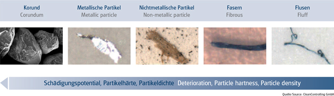
Selected Types of Particles
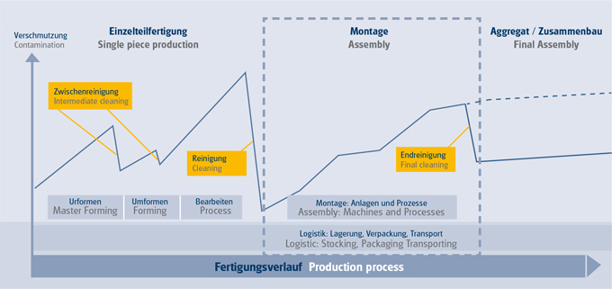
Particle Volume in Production
Quality problems – customer complaints; excessive scrap rates; increased reworking outlay – often only become apparent in the course of an ongoing production series; mostly during or following the start-up phase.
In many cases the cause is contamination during the manufacturing process. The sources of such contamination are diverse: insufficiently cleaned primary materials or dirt particles originating during the process such as swarf, ridges or flaked off particles. In such cases use of pre-, interim or post-cleaning can quickly pay off. In order to enable existing process layouts to be retained Dr. Escherich offers integrated systems for surface cleaning.
Particle size & filtration systems
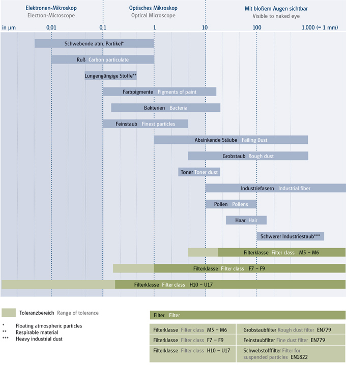
Falling Particles
Coarse particles between 50 μm and 1 mm in size can be detected by the naked eye. Among these are, for example, heavy industrial dust from the production, hairs, pollen, industrial fibres etc. These are generally termed coarse dust. Smaller particles from 50 to 0.1 μm can only be seen through a microscope, including bacteria, paint pigments etc. These are generally termed fine particles. These particle sizes correspond to filter classes M5–M6, F7 they are, however also retained by the considerably finer filter classes F8–F9 and E10–U17.
Constantly Floating Particles
Particles which no longer sink but float constantly in the air are of a size below 1 μm. These particles count among the respirable matter. Among these are soot and finer metallurgical dust. Particles with a size of more than 0.1 μm and less than 10μm are retained by filters of the filter classes F8–F9, but classes E10–U17 also filter these particles.
Finest Particles
Particles less than 0.1 μm can only be detected by special microscope like electron microscopy. Fine, floating particles and aerosols are between 0.01 μm and 0.1 μm in size.
Only HEPA and ULPA filters of the E10–U17 are capable of filtering these particles. Particles below 0.01 μm can be partially filtered by active carbon.
Implementation of cleaning tests
The customer’s components can be tested in the factory-owned test set-up related to cleanability. Thereby it is determined, which cleaning process is suitable for the cleaning result as desired. The choice of the required system for the removal of electrostatic charges and the surface contaminations is usually done by the application, part geometry and the adhesion of the particles on the surface. A multitude of different cleaning systems are ready.
Test set-ups with contact and contactless cleaning system for flat or 3D surfaces are ready.
The pilot survey is a reflection of a potential cleaning system and the test results are approaching to the future cleaning results.
The evaluation can be carried out by an approximate analysis for example by a microscope locally right after the test or external by a laboratory for example according to VDA19. The cleaning results indicate the basis for the choice of a standard solution or a product- and customer-specific adaption.
Please coordinate the laboratory setup and procedure with your contact partner.
Experiment process
(Please observe the following information to ensure a trouble-free laboratory process).
Number of trials
The number of trials depends on the type and characteristics of the components. Pease coordinate the exact number with your contact partner.
In general the components to be tested should be taken from current production under normal conditions. Please use suitable gloves to handle the components and pack the components individually in a plastic bag.
Please send us the test samples as well as the same number of a comparative group from the same batch. Test samples and the comparison group serve to compare cleaned and uncleaned components under the same conditions.
Please include in addition 1 - 2 inspection samples and a dust sample.
In the case of conveyor materials, bulk goods and other samples, coordinate the number and type with your contact person.
Packaging for transport
When dispatching the components, ensure that the packaging is suitable. It must be assured that no additional contamination reaches the component. The components should be so packed that as few particles as possible are generated in transit. Stabilise by using filling material or individual packaging of the components (no direct contact with the components). We recommend separate packaging of components in clean PE bags. Cartons are not suitable as direct outer packaging.
Required accompanying documents
Please enclose with the test samples following information:
Project name
Drawings or numbers of the parts
Please make a note on the deliver papers of your contact details and the name of your contact partner here in our premises.
Please list further product-specific information’s on the accompanying documents which you get from your contact person.
Dispatch
Please send the test samples to the following address:
Dr. Escherich GmbH
Oberflächenlabor
Lockwitzgrund 100
01257 Dresden
Germany
Please make a note on the deliver papers of your contact details and the name of your contact partner here in our premises.
Process time
Please coordinate the process time with your contact partner.
Note
All information received in the course of the examination will be handled confidentially.
Particel measurement
Process of Particle Measuring Conforming to VDA 19.1
Due to the extensive range of possible applications of Dr. Escherich cleaning methods, the analysis methods must be chosen carefully, since the limits of measuring technology can partially fall short with regard to particle size and particle numbers. The existing standards can not be applied for all requirements; they are, however very useful as aids.
Component cleanliness analyses can be used for checking effectivity of a cleaning process. For this, the starting condition of the components before the cleaning process is recorded and compared with the analysis results after the cleaning process.
Information required for component cleanliness analyses
Before beginning the component cleanliness analysis, existing standard of cleanliness requirements for the component to be examined must be established, in order to define the required examination steps.
Process of a component cleanliness analysis
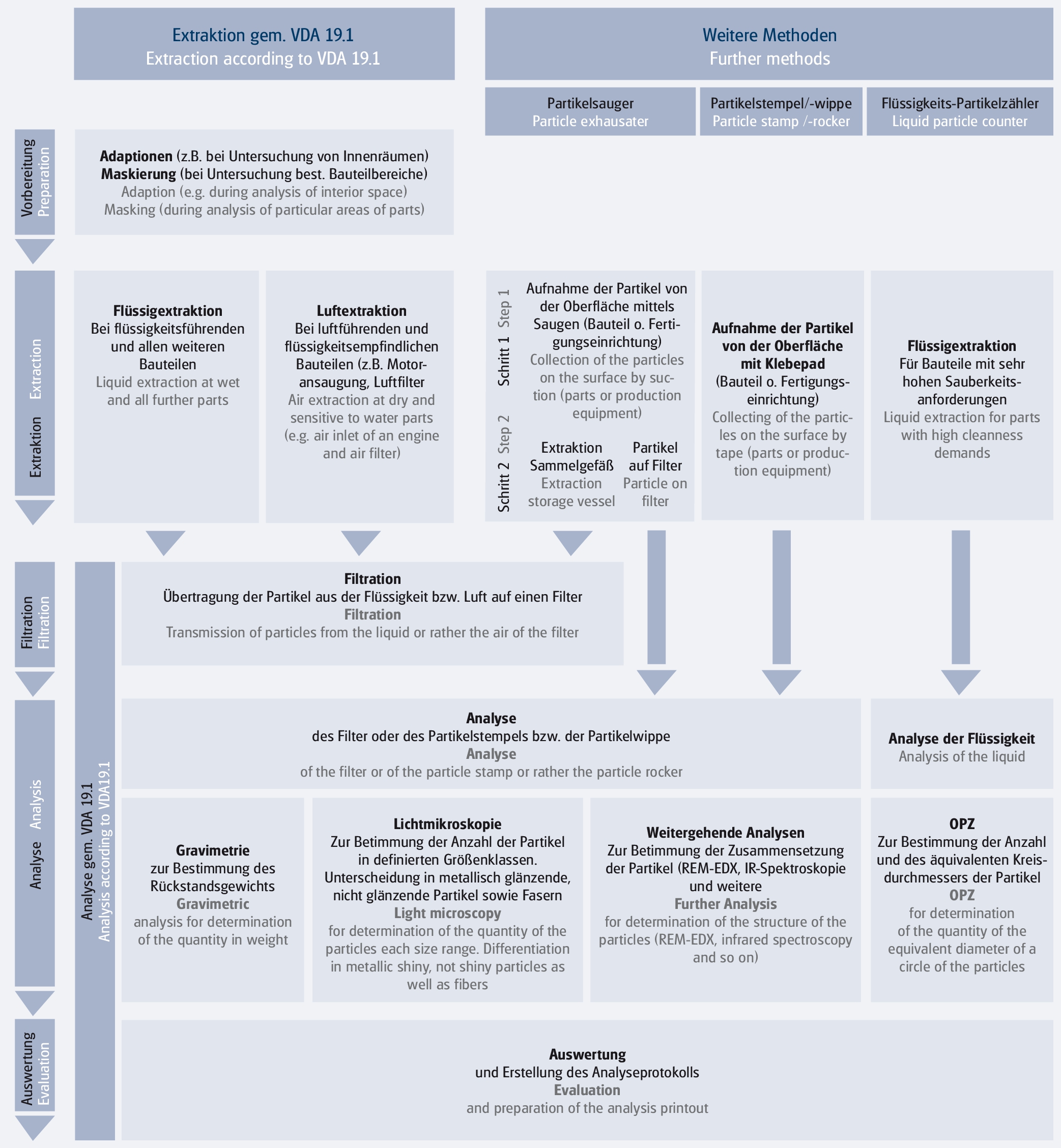
In order to evaluate the component cleanliness, several steps must be taken in sequence (see diagram Examination Methods).
Examination methods
The 5 examination steps shown in the diagram
1. Preparation
In the case of complex components, whose interior surfaces or only partial areas are to be analysed, it may be necessary to construct adoptions or masking. These help to minimise the risk of adding transferred contamination from component areas which are not relevant into the analysis results.
2. Extraction conforming to VDA 19.1
By means of a cleaning step using a test medium, the particle contamination of test components is released. Conditional is that in the extraction it must be taken into account with which medium the component comes into contact in its later application and whether the stability of the component material relative to the test medium is assured. It can be extracted with liquid or air or other test procedures can be adopted.
PRECONDITIONS OF EXTRACTON
In order to ensure that the component cleanliness is correctly evaluated, there are two preconditions. For one it is necessary to examine the testing equipment for its suitability by means of the blank value determination, for the other the extraction parameters for each component must be examined for their effectivity by means of a qualification examination.
DETERMINATION OF THE BLANK VALUE
The blank value describes the total value of the contamination which due to the testing environment can access the equipment used, affecting the end result, and which results from handling of the test sample during the test, but does not originate directly from the component. An examination of the blank value is necessary before each performing component cleanliness analysis, in order to ensure that the requirements stated can be achieved. This blank value criterion conforms to each of the required standards of cleanliness. As a result, with increased requirements of cleanliness, also increased requirements for the test equipment used and the testing environment must be also be applied. The fewer the particles of a product are permitted, the greater is the risk of influence on the analysis result due to particles which occur during testing which do not originate from the component.
QUALIFICATION OF THE TEST PROCEDURE
Qualifying the test procedure serves the purpose of determining the extraction procedure most suitable for the component and confirming that the relevant particles located on the component have been completely captured. Without qualification of the test procedure it is not assured that all relevant particles - and only these, not additional ones released from the product surface - are released and captured. With the qualification, the test specification is drawn up in which all relevant parameters of extraction processes are defined, according to which the components are tested.
EXTRACTION WITH LIQUID
Extraction with liquid is the medium of choice when components are tested which carry liquids. Particles are released by mechanical or chemical means. When choosing the extraction medium, the history of the component must be taken into account, since the accompanying contamination (e.g. cooling oil, preservatives, washing media and working materials) strengthen the adhesion of particle contamination.
EXTRACTION BY AIR
Air as a test medium is used for components which, during their manufacture or in their later function do not come into contact with liquids, or could be damaged by liquids. These could be electronic components or components of the engine air input system, e.g. air filters. If in the case of these components it is possible to avoid the chemical solubility of the liquid, extraction by air offers a good alternative to the liquid based extraction process.
OTHER TESTING METHODS
The extraction processes described in VDA 19.1 can now, for instance no longer necessarily be used for components of large devices, since there are no corresponding extraction systems on the market or the investment required for such systems is enormous. In the case of production systems it is interesting which cleaning standard these could correspond to and what contamination potential could exist. In order to answer these questions there are aids with which, in fact, only partial test samples could be taken. On the other hand, however, with VDA 19.1 analysis, processes can be evaluated. Examples are particle suction devices or particle stamps.
3. Filtration
We have previously mentioned the term analysis filter. In order to analyse the extraction media of existing particles gravimetrically or microscopically, they must be transferred to an analysis filter. In the standard process, filter membranes are used with a diameter of 47 mm with various mesh/test sample sizes. The choice of mesh/test sample size is based on the smallest size of particles to be collected.
4. Analysis
A variety of analysis processes can be used to ascertain the particulate load, the size of the particles and the number of particles in each size classification.
It is important to know in advance what information you wish to acquire by the analysis, since this is decisive for the choice of analysis process.
FURTHER ANALYSIS
Further Analysis are e.g. scanning electron microsopy and liquid particle counter.
5. Evaluation
When evaluating analysis data it is usual to state the number of particles per size classification. Size classes are defined in VDA 19.1 or are provided by the customer.
Furthermore, the number of particles per size class is relative to a standardised surface of 1000 cm2. This eases the comparability of technical cleanliness between different components.
The largest particle is often also recorded. It should be noted, however, that the length of the largest particle is subject to considerable fluctuation.
Recommended is evaluation of the cleanliness quality of a surface by totalling the particle number of several size classes, e.g. all particles > 50 μm.
Information to particel measurement
Technical cleanliness
For technical cleanliness of components it must be borne in mind that it is not a matter of a component’s feature (e.g. a size) but rather a condition. The difference between a feature and condition is that a feature can be purposely produced. Conversely a condition can indeed be aimed at, but not accurately produced.
How many components or how much component surface is requires for the test?
Due to the issue of blank value, for analysis at least 200 cm2 of component surface is necessary. Several components can be necessary for small and very clean components. To achieve a statistically significant result it is also useful to match the test batch size to the size of the product batch.
In case of component surfaces less in size to the recommended 200 cm2, analysis is possible in principle; it involves, however, more complications with regard to cleanliness of the extracting equipment and the extraction environment.
Dealing with fibres
The influence of textile fibres in production processes can only be accomplished with the aid of a clean room environment. In the automotive industry, fibres and fluff are not usually regulated because of their low detrimental potential; they are, however, documented in analysis results. If it is necessary to register fibres correctly and count them, for technical analysis, due to the blank value problematic, more complicated work is needed than that described in VDA 19 part 1. This must therefore be taken into consideration previous to testing.
It is important that fibres are correctly identified and categorised in the analysis. Due to their length of up to several millimetres, fibres which are not correctly registered can lead to non-conformity of cleanliness demands.
Dealing with particles < 50 μm
For particles < 50 μm the testing procedure described in VDA 19.1 is only suitable to a limited extent, as it is difficult to assure a blank value. In order to achieve this low blank value requirement, greater demands must be made on the equipment used and, above all on the testing environment (clean room conditions). For this it can be necessary to provide ultra-clean workplaces (flow boxes) and to reduce to a minimum the surfaces in the laboratory which come into contact with extraction liquids.
Dealing with complex components
In the case of geometrically complex components, complex assemblies or components which must be activated during the test, it must be taken into account that the cleanliness analyses can be very complicated. Firstly it can be necessary to employ additional aids such as photographs (fixtures?), mountings, manipulators and adaptions. These components often need to be specially adapted/manufactured for the test component. Similarly the time and medium requirements increase for large components with several or large-volume interiors. For all these complications it must, however, be assured that the required blank value criteria are fulfilled. It must furthermore be taken into account that in the extraction procedure, particle contamination in indentations can be difficult to identify.
Differences in particle measurement
Due to differing measurement principles, analysis results of different measuring procedures can not be directly compared. In the case of microscopic procedures (by optical microscope or scanning electron microscope), size measurement of particles is made using feretmax criteria to determine the actual length of the particle. Measuring systems which operate according to the shadowing principle determine the size of the particle by means of the equivalent diameter. The shadowed surface is converted to a circular area and then the diameter of the circle is given as particle size. If the particles are minute this is not critical, since with reduction of size, particles become ever more compact (rounder).
About us
KIST + ESCHERICH GmbH optimizes the production processes of internationally known manufacturers by avoiding and removing contaminated surface particles.
We are specialized in surface-cleaning & web-cleaning, de-dusting, particle cleaning, components & part cleaning, as well as cleaning machines & cleaning equipment using electrostatics, ionization & discharge of components. Especially the removal of dust, particulates, fibers & production residues of assemblies, components. Enrichment of laminar air-flow.
In particular, the removal of dust, particles, fibers & production residues of assemblies, components, small parts, plastic parts, industrial parts, decorative parts, bulk material. As well as film, web, foil, sheets, material web, plates, printed circuit boards, PCB, connectors, circuit boards, tray, small load carrier, SLC container, blister, packaging materials, work piece carriers, transfer systems, conveyor belt, transfer systems, transport belt.
Solutions for requirements out of the VDA19 as cleanliness analysis and inspections, contamination analysis and more answers in the field of technical cleanliness of components.
With our solutions, we remove particles, improve product quality and reduce scrap rates.
CONTACT
KIST + ESCHERICH GmbH
Höglwörther Straße 1
81369 Munich • Germany
![]() +49 89 318 555-0
+49 89 318 555-0
NEWSLETTER
Keep up to date with industrial component cleaning: